Autodesk Moldflow Adviser
Helps you to reveal, communicate and solve part defects in the first stage of product development.
Design of plastic parts and injection molds
Adviser is an intuitive tool of simulation. It enables a quick view of cavity filling and basic aspects of part manufacturability. It shows results with comments and recommendations on how to solve problem and facilitate manufacturability. With Moldflow Adviser you can
- Localize the problem in the part
- Get advice how to cure it
Video Autodesk – Adviser for the designer.
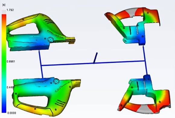
Melt flow simulation
Flow analysis
Melt flow simulation helps optimize a part as well as a mold, reduce defects and improve process parameters.
Part defects
Simulation reveals defects like weld lines, air traps and sink marks and enables to change the part design to minimize them.
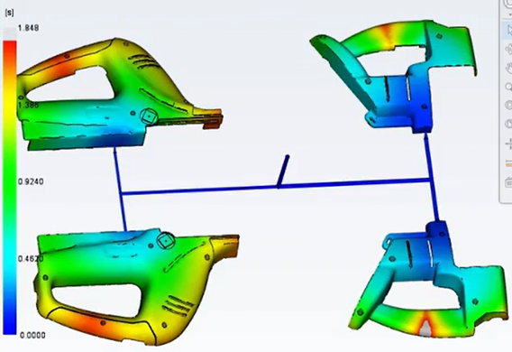
Cavity filling
Cavity filling simulation enables to predict melt behaviour and uniform cavity filling, to avoid short shots and eliminate, minimize or shift weld lines and air traps.
Packing
Simulation enables to optimize packing and visualize range and layout of volumetric shrinkage which helps to minimize part warpage and deflection and part defects like sink marks.
Runner system simulation
Feed system
Simulation enables to design and optimize hot and cold runner system and to set gate locations as well as to improve part surface, minimize part deflection and reduce injection cycle time.
Gate location
Simulation identifies up to 10 gate locations at the same time. You can minimize injection pressure and eliminate defined areas from gate location.
Runner system design
After setting layout, size and type of components like a nozzle, channel or gate you can create a runner system.
Runner system balance
Helps to balance a runner system for a simple, multi-cavity as well as family mold so that all parts/cavities are filled simultaneously (only 1 gate/1 cavity), stress values and material consumption are reduced at the same time.
Hot runner system
Design of hot runner system components.
Mold cooling simulation
Cooling system
Helps to make cooling system more efficient, to reach high quality of view surfaces and to reduce cycle time.
Design of cooling system components
Enables to analyze cooling system efficiency and to design cooling circuits, baffles and bubblers.
Cooling system analysis
Enables to optimize mold and cooling system design to achieve uniform cooling of the part, to minimize cycle time, to reduce part deflection and production costs.
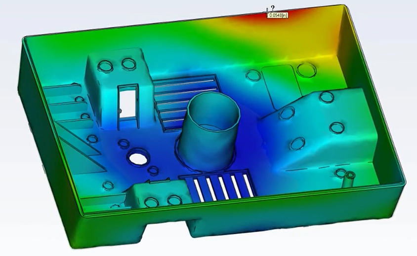
Shrinkage and warpage simulation
Shrinkage
Evaluates part and mold design from shrinkage and warpage point of view.
Shrinkage
Helps to meet size tolerance limits of the part by shrinkage data from process parameters and specific material data.
Warpage
Predicts warpage following from stress during injection process. By simulation we identify where warpage can occur and we adjust part and mold design, material choice and process parameters to minimize part warpage.
Video Autodesk – Part tolerance shrinkage and warpage.
Fibre orientation
Enables to check orientation and distribution of fibres in plastics and therefore to reduce part shrinkage and warpage.
CAE – Data Exchange
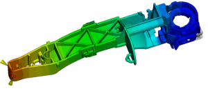
We can evaluate and optimize plastic part design also using data Exchange with structural simulation software. CAE data Exchange is done with structural simulation software Autodesk® Inventor Nastran, ANSYS® and Abaqus®. Structural analysis clarifies effect of processing on properties of injected plastic parts filled with fibres under working load.
Connection with CAD systems and networking
Tools for an original CAD model conversion and optimization. Help at solving thin wall parts as well as thick volume parts. Mesh type choice based on required accuracy and time length of simulation.
CAD solid models
You can import and mesh geometry as solid created in Parasolid®, Autodesk® Inventor®, CATIA® V5, Pro/ENGINEER® and SolidWorks® CAD systems as well as in universal formats IGES and STEP.
Error check and correction
You can scan imported geometry and correct errors emerging from the part transfer from CAD sw automatically.
Axis Import/Export
You can import and export data of axes of runners and cooling channels to and from CAD sw to shorten design time and to eliminate errors emerging from designing of runners and cooling channels.
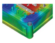
3D simulation
3D simulation on complex geometry using tetrahedral mesh of final elements. Optimum for electric connectors, thick-wall components or geometry with different wall thickness.
Dual Domain Technology
Solid models of thin-wall parts can be simulated using Dual Domain™ technology. You can work directly from 3D solid CAD models, which leads to more simple analysis of repetitive design elements.
Evaluation of results and efficiency
You can visualize and evaluate simulation results and use tools to create reports automatically. There is a material database and costs saving advisor that helps increase efficiency.
Result presentation and explanation
You can use comments on results at each single site of the model to solve a problem as fast as possible and to report the chosen solution.
Result explanation
When clicking at each single site of the model you can easily identify reasons of short shot, wrong part design or bad cooling. You will get proposals how to modify a part design, mold or process.
Automatic report generation
You can use a Report Generation Wizard – a tool to create a final report where you prepare and share simulation results with your customers, suppliers or your team.
Microsoft® Office
You can export results and pictures to create reports in Microsoft Word and presentations in PowerPoint.
Autodesk Moldflow Communicator
Enables to share and communicate data by one single tool to all participants – engineering, production, suppliers and customers. By means of Autodesk Moldflow Communicator you can show and export simulation results to company management as well as to a Customer, visualize them, quantify and compare them easily.
Installation file: here
English tutorial: here
Material data
Simulation can be more precise when using measured material data. Data measurement can be provided.
Material database
The software includes database of 10 000+ polymers with material characteristics for injection molding simulation.
Tools to increase productivity
Design Adviser
Results Adviser
Comments explaining the showed result with relevant context including information on what to focus on, what to search for and how to heal typical troubles. You can also find out more on sover theory, simulation results interpretation and how to design plastic parts and injection molds. Komentář podávající odborný výklad k problematice zobrazeného výsledku, zasazený do příslušného kontextu, včetně informací na co se zaměřit, co hledat a jak opravit typické problémy. Můžete se také dozvědět více o teorii řešičů, interpretaci výsledků simulace a jak lépe navrhovat plastové díly a vstřikovací formy.
Costs Adviser
You can find out how price of the part is calculated and to minimize costs. You can also estimate production costs on basis of mateial choice, cycle time, possible operations after ejection and fixed costs. Můžete zjistit, jak se tvoří cena dílu a tuto cenu minimalizovat. Dále odhadnout výrobní náklady na základě volby materiálu, času cyklu, případných operací po vystříknutí dílu a fixních nákladů.
Autodesk Moldflow Insight
A tool for simulation of the whole injection molding process enabling deep analysis in the stage of development of the product and the tool.
- Software Autodesk Moldflow Insight enables to solve, evaluate and optimize a plastic part as well as injection mold and helps study traditional as well as the most advanced injection molding processes.
- Simulation of most advanced injection molding technologies
- The most reliable results of simulation of parts with the most complex geometry
- The largest database of polymer materials for plastics injection molding
Simulation results show you how changes of part design, mold geometry and process parameters affect manufacturability of your part. Výsledky simulací vám ukážou, jak změny v designu dílu, geometrii formy a procesním nastavení ovlivní vyrobitelnost vašeho dílu.
Software Autodesk Moldflow Insight is used by state-of-the-art manufacturers in automotive industry, electronics, medical material and packaging not only to save costs but mainly to reach the highest quality of products and fast and efficient innovation.
Video Autodesk – Injection molding simulation tool for engineers and analysts
Simulation of thermoplastics and thermoset injection molding
Thermoplastics injection molding simulation
Simulation of thermoplastic polymer injection molding uses database of more than 10 000 polymers. Optimization of filling, packing and cooling focusing on smooth injection molding process and elimination of defects.
Thermoset injection molding simulation
Injection molding simulation of thermosets, RIM/SRIM resin transfer molding and rubber. Deep insight in polymer meshing reaction during an injection cycle.
You can simulate cavity filling with or without fibres, avoid short shots caused by preliminary thermoset meshing and to identify sink marks and risky weld lines.
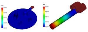
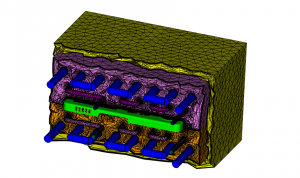
Insert overmolding
Simulates injectiom molding process effect on metal or plastic inserts in the mold cavity. You can predict deformation – bending of the connector in cavity and shift of insert caused by pressure.
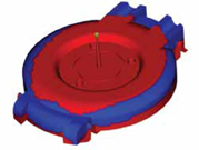
Core shift
Simulation of injection molding process effect on the mold parts that can be deformed. Based on core fixing in the mold the system evaluates shift of the loaded part.
Special injection molding processes
Simulation of wide range of injection molding processes and state-of-the-art applications.
Gas-assisted injection molding
Helps to locate polymer melt and assistence gas gate correctly, defines polymer quantity that needs to be injected before gas injection and gas effect on the injected polymer. Optimization of hollow structures.
Multi-component injection molding
Visualizes flow of both materials in the cavity and their interaction together with the resulting complex deflection. You can optimize combination of materials with regards to maximum ratio price-performance.
Injection-compression molding
Simulates simultaneous or sequential injection molding of polymer melt and packing by the mold. Evaluation of suitable polymer materials, design of the part and mold and process conditions. Suitable mainly for thin-wall parts.
Compression molding
Simulation of a traditional compression molding technology – shape forming of a semi-product in a mold cavity with pressure and temperature. Simulation of the mold temperature field and heating elements effect.
Injection with RHC technology
Simulation of intense local heating of mold surface based on heat induction or steem flow in the heating circuit. The process results in mirror-glossy surface together with no weld lines and other surface deffects elimination.
Conformal cooling
Simulation of injection molding and the mold temperature field using conformal cooling technology – cooling circuits of complex geometry.
MuCell
Simulation of formation of foam structure of plastic parts based on physical or chemical process. Process optimization with regards to part weight reduction and elimination of deffects like sink marks or undemanded deformation.
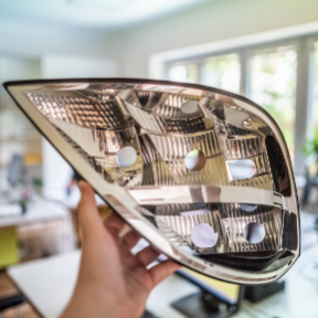
Birefringence
Predicts visual quality of the part evaluating changes of birefringence index following from stresses occuring in the part during injection molding process. The sw evaluates different polymer materials, process conditions, location of the gate and channels and helps to check birefringence of the part and therefore the visual purity of the part.
Connection with CAD systems and networking
Tools for transition and optimization of the original CAD model. Help to solve geometry of thin-wall parts as well as high-volume applications. Choice of mesh type based on demanded analysis precision and length of simulation.
https://www.autodesk.com/products/moldflow/features
CAE – Data Exchange
We can evaluate and optimize plastic part design using data exchange with the sw for structural simulation. CAE data exchange can be done with Autodesk Inventor Nastran (Nastran In-CAD), ANSYS® and Abaqus®. Structural analysis clarifies processing effect on properties of injection molded parts filled with fibres under work load.
Autodesk Helius PFA is a tool to map Moldflow results to the sw for structural analysis.
CAD solid models
You can import and mesh geometry in solid format made in CAD systems Parasolid®, Autodesk Inventor, CATIA® V5, Pro/ENGINEER® and SolidWorks® as well as in universal formats IGES and STEP.
Error check and correction
You can scan imported geometry and correct errors emerging from the part transfer from CAD sw automatically.
Axis Import/export
You can import and export data of axes of runners and cooling channel elements from and to CAD software to shorten design time and to avoid errors.
Modification of CAD surfaces in Moldflow
Use Modify CAD Surfaces tool to do design optimization without exporting your model to CAD to modify it and then re-import.
CAD Doctor for Autodesk Moldflow
A tool to check, correct and simplify a solid model imported from 3D CAD systems so that it is ready for simulation. Product of Elysium Inc. company. More information upon demand.
3D simulation
3D simulation on complex geometry with the method using tetrahedral mesh of final elements. Best for electric connectors, thick-wall components or geometry with different wall thicknesses.
Dual Domain Technology
You can simulate solid models of thin-wall parts using Dual Domain method. You can work directly from 3D solid CAD models, which leads to more simple analysis of repetitive design elements.
Mid-plane mesh
Enables to generate 2D midplane surface mesh with defined thicknesses for thick-wall parts.
Tools for evaluation of results and productivity
You can visualize and evaluate simulation results and use an automatic tool to generate reports. There is a polymer database available and an advisor for costs savings that helps to increase your efficiency.
Presentation and evaluation of results
You can use comments of results at each single site of the model to find the fastest solution and report it.
Automatic generation of result reports
You can use Report Generation Wizard – a tool to create a final report where you prepare and share results with your customers, suppliers and your team.
Microsoft® Office
Export results and pictures to create reports in Microsoft® Word and presentations in PowerPoint®.
Autodesk® Moldflow® Communicator
Enables to share and communicate data by one single tool to all participants – engineering, production, suppliers and customers. By means of Autodesk Moldflow Communicator you can show and export simulation results to company management as well as to a Customer, visualize them, quantify and compare them easily.
Installation file: here
English tutorial: here
Material database
The software includes database of 10 000+ polymers with material characteristics for injection molding simulation.
Material data
Simulation can be more accurate with update and complete material maps achieved by material data measurement. With specific material characteristics you get a more accurate prediction of injection molding process, process parameters proposal and strength and behaviour of the plastic part.
Upon your interest we provide material properties measurement of your polymer. Material data measurement and following Moldflow data file generation with measured data.
Tools for result evaluation and productivity increase
Help
Comments explaining in detail the displayed results with relevant context including information on what to focus on, what to search for and how to solve typical problems. You can also find out more on solver theory, simulation result explanation and tutorial how to design plastic parts and injection molds better.
Automatization and customization
You can automate routine tasks and customize Autodesk Moldflow sw to your company needs.
Application Programming Interface
Application Programming Interface (API) extends functionality of Autodesk Moldflow and enables to automate routine tasks, adjust user interface, work with third-party applications and implement company standards.
https://knowledge.autodesk.com/support/moldflow-insight/learn-explore/caas/CloudHelp/cloudhelp/2019/ENU/MoldflowInsight-Linux/files/GUID-087B8880-3575-4B72-951C-108ABDBE2F3A-htm.html
User Interface
User interface and application properties can be customized upon your requirement. User profiles can be set from beginners to introduce them to simulation analyses and to identification of common problems. More experienced users can have their profiles defined with more functionalities and flexibility.
https://knowledge.autodesk.com/support/moldflow-insight/learn-explore/caas/CloudHelp/cloudhelp/2019/ENU/MoldflowInsight-NewUser/files/GUID-645CE8B5-BCD2-44D6-B153-F88546CB5B00-htm.html?v=2019&st=user%20interface